You have 0 items in your cart
RD Mathis Company Technical Library Publications
info@rdmathis.com | www.rdmathis.com
![]()
Problems in achieving pinhole free dielectric films have, in many cases, stemmed from ejection of particles from the source. This problem has been overcome by several different evaporator designs, all of which incorporate one basic design consideration; namely, elimination of a direct line of sight from the evaporant to the target. [1, 2]
In general, these evaporators incorporate designs which are a marked improvement over exposed source designs. However, under conditions of high evaporation rates, ejection of small particles still is noted to occur. Also, maintenance-problems occur for two primary reasons:
The evaporator described in these discussions was conceived with three special design features in mind.
To ensure a particle-free vapor stream, the evaporator was designed with two baskets at either end of the evaporation chamber as shown in Figure 1. As shown in the figure, a baffle extending down from the cover completely surrounds each basket. The center portion of the chamber is open. Centered above this vapor chamber is a round chimney opening in the cover through which the vapor stream passes.
In addition to the baffles around the silicon oxide baskets, the cover has a lip which fits snugly and overhangs the evaporation chamber on both sides. The ends are sealed as the cover and evaporation chamber clamp together to form the electrical terminations of the evaporator. Thermal shielding surrounds the evaporator and is attached so that the shields do not produce undesirable cold spots in the evaporation chamber.
The unit as described in Figure 1 is 3-1/2 inches long overall, 1 inch wide and 1 inch deep. The actual evaporation chamber is 2-1/2 by 3/4 by 3/8. Both baskets together contain 5 grams of silicon monoxide.
Because the unit has low thermal mass and is designed to run hot in all areas, condensation of evaporant is kept to a minimum and the unit remains remarkably clean even after continuous use. Therefore, reloading is readily accomplished by unclamping the ends, raising the lid and refilling the baskets.
The unit has been successfully operated over a wide range of evaporation rates and considerably higher rates are contemplated for the evaporator. Typical data are summarized in the graph in Figure 2. The area to the left of the dotted line represents formation of films with very high transmission and practically no color in thicknesses of 8000 angstroms or less when evaporated at pressures of 1 x 10⁻⁴torr. Such films are approaching SiO2 in composition. On the other hand, films represented by the right side of the graph are more nearly SiO in composition and appearance.
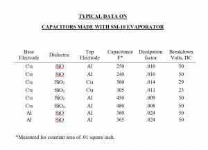
Capacitors have been made using aluminum and copper electrodes with the evaporator. Typical data are shown in Table I. In general, greater success has been achieved with aluminum top electrodes, or aluminum top and bottom electrodes than with, gold or copper. The evaporator has been used successfully with high yield in the fabrication of RC circuits employing NiChrome film resistors and silicon monoxide capacitors.
One typical circuit contains 12 capacitors ranging in value from 400 to 1200 Pico farads and 12 resistors. The circuit is designed for operation at 200 megacycles. Another circuit made with the evaporator has operated at frequencies to 900 megacycles. In the fabrication of these circuits, a source to substrate distance of nine inches was used.
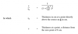
Distribution from the evaporator was studied in a plane at a distance of nine inches from the source. The thickness variation as a function of distance from target center directly over the source is shown in Figure 3. Figure 4 compares this thickness distribution with typical published data by Stekelmacher and Holland [3] for distribution from a point source. The curves are based on Knudsen’s law [4] and the relationship:
The evaporator design has achieved the objectives desired, namely a particle-free vapor stream, ease of filling and maintenance, and a wide range of evaporation rates. Because of the design, the unit can also be operated upside down with a minor change in the baffling. Also, with the two sources feeding one evaporation chamber, it is conceivable that this type of evaporator can be used for co-evaporating two different materials.
Written By
Earl Olson
HALEX, Inc.
139 Maryland Avenue
El Segundo, CA 90245
Distributed By
RD Mathis Company
2840 Gundry Ave Signal Hill CA 90755
Phone: (562) 426-7049 | Fax: (562) 595-0907
TABLE I
TYPICAL DATA ON CAPACITORS MADE WITH SM-10 EVAPORATOR